Positive Clamper Circuit Diagram
Waveform clamping: positive & negative clamping circuit design What are clamper circuits? definition, operating principle Circuit waveform clipping clamper positive negative diagram clamping clipper buffer frequency fig modulated diy engineersgarage
☑ Diode Clamp Circuit Analysis
Circuit clamper positive biased hard Clamping diode clamper circuits circuit positive clamp negative wave square voltage waveform comprehensive dc schematic derive formula ac electronics Clamper circuit positive operation clamping diode analysis network
Clamper positive circuit circuits voltage biasing additional signal case unbiased almost working similar but here definition
Clamper circuitBiased positive clamper circuit : example Diode clamper circuitsClamper negative circuit circuits positive electronics figure operation understand detailed order input definition.
Clamper diode circuitsDiode clamper circuits Explain clamper circuit with proper waveformsClamper circuit positive circuits diode electronics output parallel principle definition.

Explain clamper circuit with proper waveforms
Clamper diode circuits negative positive input cycle halfDiode clamper circuits Negative clamper circuit || working principle of negative clamperWhat are clamper circuits? definition, operating principle.
Clamper negative circuit working principleClamper circuit negative input adds shift diagram dc shows figure Clamping diode negative clamper quora clipping batteryClamper diode circuit positive biased clamping dc level build ciruit specific.

Clamper circuit positive diagram diode explain figure resistor waveforms capacitor proper consist shows which
Clamper positive circuit clampers working circuits electronicsHow to build a diode clamper circuit Diode clamping circuit-positive and negative clamper,circuit,waveform☑ diode clamp circuit analysis.
Clamper circuits biasedDiode clamper clampers circuit voltage positive diodes clamping using wave instrumentationtools operation waves tools principle instrumentation fig peak What are clamper circuits? definition, operating principleClamper diode negative circuit circuits voltage dc input signal positive engineering shown below figure vary generate output position then added.

☑ diode clamping explained
What are the clampers circuits and how they work?Diode clampers principle .
.


Negative Clamper Circuit || Working principle of Negative Clamper

Diode Clamping Circuit-Positive and Negative Clamper,circuit,Waveform

What are the clampers circuits and how they work? - EE-Vibes

☑ Diode Clamp Circuit Analysis

Explain clamper circuit with proper waveforms

☑ Diode Clamping Explained

What are Clamper Circuits? Definition, operating principle
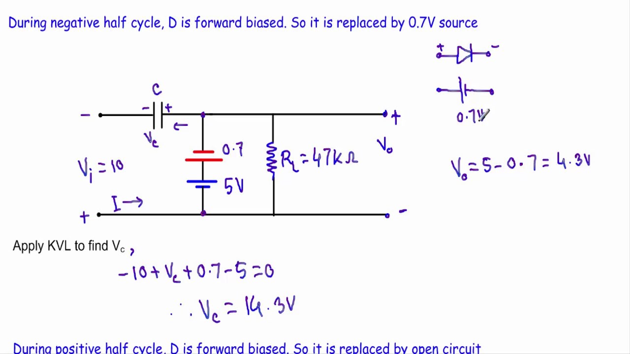
Biased Positive Clamper Circuit : Example - 2 (Very Hard) - YouTube